Notice
Applications
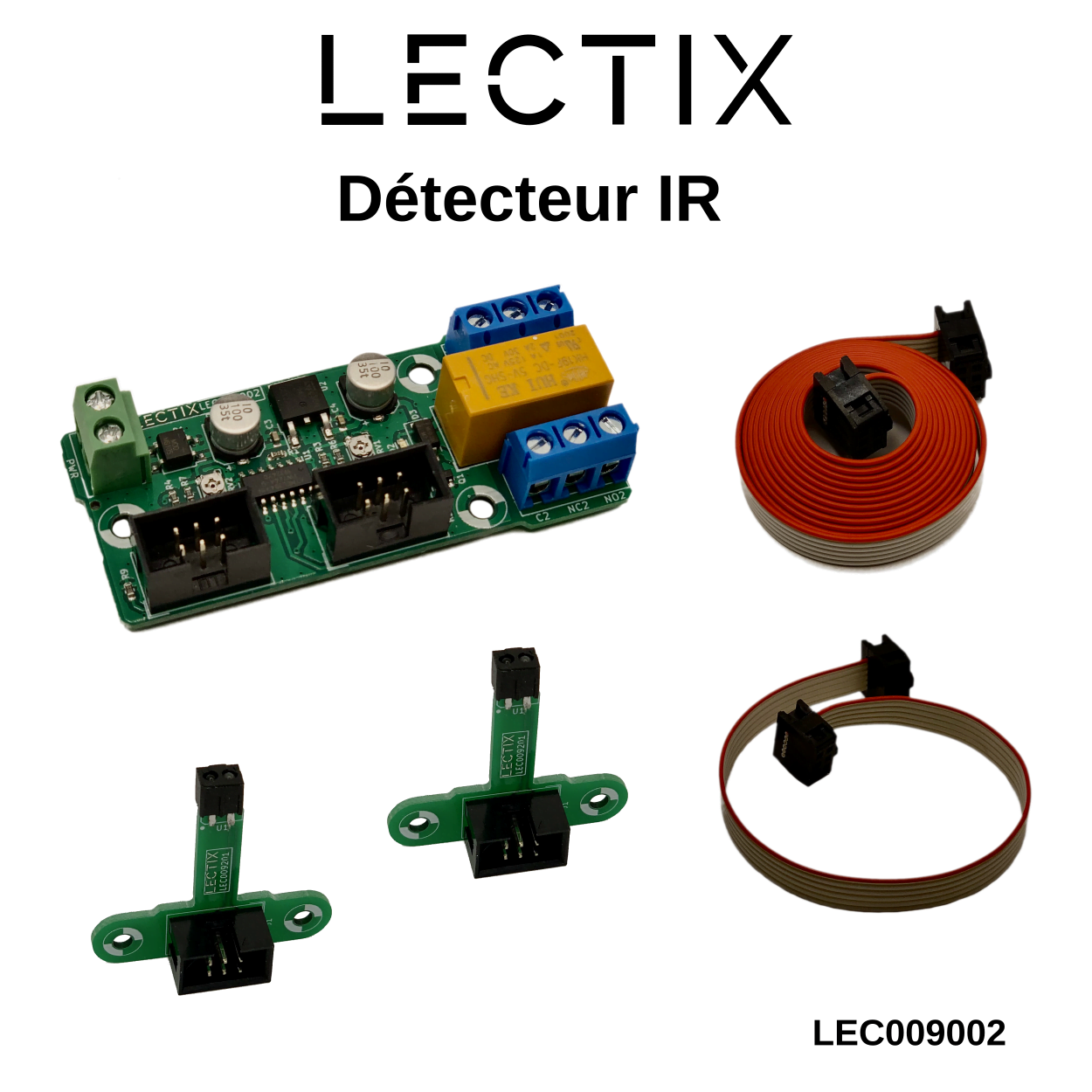
The LEC009002 module is an Infrared (IR) detector that detects any object in the vicinity (train, cars, …), without requiring any changes in the track cabling!
Use 1 or 2 sensors, according to your convenience, to detect your rolling stock (trains, bus system, …), or any other object near the sensors.
The relay's contacts present on the module allow a very generic use. Some cases of use are listed below.
Use 1 or 2 sensors, according to your convenience, to detect your rolling stock (trains, bus system, …), or any other object near the sensors.
The relay's contacts present on the module allow a very generic use. Some cases of use are listed below.
- Automatisms (level crossing, sound effects,…).
- Signage.
- Turnaround loop.
- Hidden tracks management.
1-sensor operating mode
When only one sensor is connected to the module, regardless of which connector it is connected to, the IR detector is in direct mode.
In this mode, the relay will be activated as soon as an object passes in front of the sensor. When the object leaves the sensor's field of view, the relay will be released after a short delay.
This time delay avoids unwanted switching on due to discontinuity of the detected object (example: spacing between cars).
2-sensor operating mode
When 2 sensors are connected to the module, it is in a bistable mode
In this mode, the detector will engage the relay as soon as an object passes in front of 1 of the 2 sensors. The relay will be released only when the object passes in the field of vision of the second sensor.
In this mode, the detector will engage the relay as soon as an object passes in front of 1 of the 2 sensors. The relay will be released only when the object passes in the field of vision of the second sensor.
Wiring
To start up this module, simply connect a power supply between 8 and 20 V DC to the power supply terminal block and you're done!
The power supply terminal is not polarized, so you can connect the – and + of the power supply as you wish. All you have to do is connect the sensor(s) via the supplied cable and your module will be ready to use.
The power supply terminal is not polarized, so you can connect the – and + of the power supply as you wish. All you have to do is connect the sensor(s) via the supplied cable and your module will be ready to use.
Sensor installation
The sensors have been specially designed to be easy to install. Their dimensions are given in the following image in mm.
To ensure optimal operation, it is recommended that the sensors be installed under the following conditions:
To ensure optimal operation, it is recommended that the sensors be installed under the following conditions:
- Integrate the sensor directly into the track, or alternatively aim it at the bottom of the wagons, so that even convoys with flat wagons can be well detected.
- Try to ensure constant lighting as much as possible.
- Adjust the sensitivity of the sensors under maximum ambient light conditions.

Set the detection distance of the sensors
The detection distance may vary depending on the color of the object passing the sensor.
To ensure optimal performance, we recommend that you make this adjustment with a black object.
The detection distance can then be adjusted by placing the object at the desired distance from the sensor, and by carefully adjusting the potentiometer associated with each sensor as shown in the figure opposite.
For ease of use, it is recommended that this adjustment be made with only one sensor connected at a time.
To decrease the detection distance, turn the potentiometer clockwise.
To increase the detection distance, turn the potentiometer counterclockwise.
Note : The potentiometer is very fragile. Never force it to deteriorate or make the module inoperable.

Examples of use
Automatic sound triggering
This diagram shows how to interconnect the IR detector with the LEC008011 sound module.This assembly can be used to trigger a sound in an automatic way (ex: a horn at the entrance of a tunnel, …)
DCC turnaround loop
This simple setup shows how it is possible to manage a DCC turnaround loop with this IR detector.The principle is to use the relay to reverse the current on the loop channel. We place an IR sensor at the loop input, and the second sensor inside the isolated channel.
Be careful to leave enough space between a sensor and the tracks breaks!


Reviews
There are no reviews yet.